Canadian getting a J1 visa
I wanted to share some of my experiences of a Canadian student obtaining J1 status. Originally, I found the information on the state websites to be somewhat contradictory. Maybe, contradictory is the wrong word, it is just that the majority of the information is obviously directed to the international community (minus Canada). There are some specifics for Canadians, but just the sheer presence of the data directed at internationals makes it easy to become uncertain about what is actually required.
When crossing the border yesterday, I had all of the information that I thought was required (see the 5 points below). The Canadian specific site claims you need (http://www.consular.canada.usembassy.gov/student_exchange_visa_usa.asp
Canadian Citizens do not need visas to study in the U.S. You do need to obtain an I-20 (or DS-2019) Certificate of Eligibility from the university that you plan to attend. At the time you receive the I-20 (or DS-2019) you will be registered with SEVIS, the student tracking system. You will be assigned a SEVIS number, and be required to pay a registration fee.
When you cross the border to study you will need to provide the Officer at the port of entry:
- Proof of identity and citizenship (a Canadian passport for example)
- The original I-20 (or DS-2019) certificate
- Proof that you have paid your SEVIS fee
- Proof that you have the funds to pay for the school that you plan to attend
- Proof of your ties to Canada
After investing more than $500-600 in the process of paying the SEVIS fee and paying for insurance, I wanted to make sure that this was adequate (i.e., no appointment was necessary at a consulate, nor any extra forms were required). For more information, I called the pay-line to get more details; I actually called twice, and both of them confirmed the above. I was still a bit tense, up until crossing the border this morning. After standing in the customs line, the first officer turned me back because I didn’t have an I-94 form filled out. Luckily this is just like the customs sheet (available near customs). After filling it out, I tried again. The officer looked over my things, stamped my passport and I-94, and I was on my way. Despite the next customs officer ping-ing me into a separate holding area where I was pong-ed immediately back out (as it was not necessary). I still wanted to make double sure, so I asked the ping-ing officer if this stamp on the I-94 was my visa. His reply, “Canadian citizens don’t get visa’s”. I had heard this somewhere else, and it is confusing, but I think this is the equivalent of visa status.
So as far as I know everything is all good.
More general information (exceptions).
http://www.consular.canada.usembassy.gov/exceptions.asp
Specifics:
http://www.consular.canada.usembassy.gov/usa_visa.asp#exchange
Total recall
About a month ago, I picked up some random books from the Wee Book Inn. I decided to take one, Total Recall, with me on my flight yesterday. When the airline announced a likely 4 hour delay due to landing gear problems, I decided to give it a go. I know what you are thinking: Total Recall, with Arnold Schwarzenegger, was based on a book? Well, no, this book is actually about memory performance–the full title is “Total Recall: How to Boost your Memory Power.” As I said, when I purchased this book, it was a random buy; I am not too worried about my memory yet. Anyhow, I got hooked on this book.
It starts out with the types of blocks that affect memory: emotional, mechanical, and physical. In this first part, Joan Minninger gives several real examples of people that have trouble remembering. These examples have the same impact as those in Dale Carengie’s seminal books, which is why I enjoyed reading it. Take one the examples for an emotional block, where a woman cannot remember her recent vacation. She wants to impress her friends, but the reason she cannot recall her vacation is because her friends are better talkers than she, and they don’t really want to listen to her stories (at least she feels this way). There are plenty of interesting stories like this, and some of them include people with photographic memories and who experience synesthesia (like Daniel Tammet).
The book then has chapters on the kinds of memory, the three r’s (registration, retention, and retrievel), and theories of how the brain works. Then the latter part of the book is about improving your memory. Many of the things you probably already know about, like association, mnemonics, and taking the information in in different forms. Some of these are specific to remembering faces/names, numbers, studying, repetition, etc. The methods for remembering information from books and lectures were presented in a way that is similar to software design patterns. The author presents several patterns of how reading material is often organized: problem pattern, opinion pattern, thesis pattern, information pattern, and instruction pattern. Most of these are probably apparent, if you thought about it long enough, but having just read a software design pattern book, I was amused at the similarities of how these patterns were presented in her writing to the software patterns.
Game Developer’s Open Source Handbook
I was recently thumbing through some books at the library, and came across the Game Developer’s Open Source Handbook by Steven Goodwin. As a longtime Open Source user, I had to look into this book to Open my eyes to some other projects.
The book as a pretty good intro to the origins of the free and open software movements as well as notes on why and when it is appropriate to use such codes in games. There is also some summaries of open source licenses and notes on when different components using different license can be mixed (and also what is required of you when you are shipping a title).
For the most part, however, I was more concerned with the tools that I hadn’t know about. The book covers development in a GNU/Linux environment. For graphics, there is info on some 2D (e.g., SDL) and 3D engines (CrystalSpace, Irrlicht, and Ogre). I was interested to find out that there was libraries mentioned in there for interactive consoles (OGLCONSOLE) and font handling. I have a small wrapper library for rendering ttf fonts in GL using freetype2, but the FTGL seems like a very worthy alternative.
There is a chapter on audio, something that I have not been too concerned with in the past. I have barely used OpenAL (in my GT racer demo), and have written to the /dev/dsp files in Linux before (NES emulator). I have also used FMOD for mp3 playback in an old bomberman implementation (I believe they have a non-commercial license). The book details some tools for sound conversion, although I pretty much always rely on mplayer, ffmpeg, or gstreamer for video and sound needs.
For physics there are also several choices. ODE is a reasonable solution (discussed in the book), which I have played around with before. I think that Bullet and Box2D were probably too recent to include in the book. The book mentions some of the other libraries useful for collision detection (e.g., OPCODE).
There are also several libraries listed for networking, including SDL_net, torque network library, and clanNetwork. I have personally never used any of these, but I figure they are probably worth looking into (although this is one of the easier areas to write your own).
Scripting was something that I was actually a bit more interested in. The book covers some of the details of using Lua, and possibly Guile (with Python, Java, and some other dynamically typed languages coming in as mentionables). I was a bit dissapointed that there wasn’t more detail in these sections, but I guess that is because it was something that I wanted to know more about.
There was a bunch of other useful utility libraries mixed in, including some for parsing xml (e.g., expat), and several libraries for GUI controls (CEGUI, SDLtk, GG, GUIChan, ParaGUI). After taking a brief look at some of these, I ranked them in this order: GG, GUIchan, paragui, SDLtk. It was interesting to find out about the generic game tree library (GGTL), and internationalization with gettext (something that I haven’t used ever, but the book provided a good enough overview of its capabilites).
Then for tools and production, some of the well known apps were mentioned (e.g., Blender, gimp, audacity, ImageMagick, ffmpeg, mplayer). Some other tools for modeling included JPatch and for film editing there was Kino and Cinepaint.
For the most part, the book brought my attention to a bunch of other middleware-like components that I either wasn’t aware of, or had forgotten about. The above list isn’t exhaustive, and I’m sure there new libraries for each of the components.
Some links
I was browsing google projects today, and I came across some things that I probably have seen before, but forgot.
- jogl: Java bindings for openGL. There is some interoperability between java and this too (swing components).
- jake2: http://bytonic.de/html/jake2.html Java port of the quake2 engine
- http://pypy.org/
- Javascript math library: http://sylvester.jcoglan.com/
- Google’s Closure: http://code.google.com/closure/
- I’m not really a javascript guy, so I don’t feel guilty for just learning about these things today.
Another boost feature that I just learnt about, that could come in pretty handy: http://www.boost.org/doc/libs/1_40_0/libs/conversion/lexical_cast.htm
Variational Displacement Map Recovery
Shortly after working on some variational scene flow (from a single moving camera), I thought it might be a good idea to implement the same ideas to reconstruct both a displacement map and a flow map on top of a base mesh. The variational formulation for displacement map estimation is more or less the same. I parameterized the displacement as displacement along the normal (something that we have done before), so the objective is to find the displacements on the mesh such that the image score is minimized (in this case, pairwise SSD scores), while having a regularization constraint over the displacements (and flow vectors) in the uv-coordinates.
I had implemented this idea, and barely tested it on anything. This last week, I figured that I could use parts of the project to generate some data. So I wanted tos hare my results. Below is a sample of three input images from a synthetic sequence. The images were lit from several lights to ensure the best conditions for the shape estimation (e.g., the SSD score wouldn’t get confused). The results look pretty good. And they should. This is a pretty good situation for stereo.

Input images for the displacement map estimation

Base mesh, rrecovered displaced mesh, and recovered displaceme map
The idea of solving for flow required that there were multiple images of the object deforming over time. Again, I tested this on a similar sequence, where now the object had some texture (to enable the flow recovery), and I also introduced some motion. The idea is now to recover both the displacement map (that ensures stereo consistency at time t=0), and also the 3D flow map that warps this image forward in time (t > 0). Ideally, there would also be some temporal consistency between flow maps at (t>0), but for now I simply solved for the displacement and flow simultaneously for pairs (t=0, t=1), (t=0, t=2), etc
In this case the input sequences look something like the sequence below:
Again, the reconstruction, for the most part was okay. There is one exception: the displaced meshes sometimes overlap/intersect, which means that they are not as useful in the application that I wanted to use them in (that is without post processing). Notice that there is flow roughly in the regions of the eyse and near the mouth, which agrees with the input sequence. The displacement looked similar to the non flowed case.

The u, v, and w- components of the flow for the last image.
The resulting, recovered mesh appears beside the input rendering in the following video. I could have probably chosen the regularization parameters better. If the video doesn’t load, try this link: flowed_result.
Spectral regularization on computer vision problems?
I recently attended a talk by Robert Tibshirani, who mostly presented his work (and related developments) of the Lasso. The talk was very interesting, but I found some of his most recent work on spectral regularization for matrix completion particularly interesting. There are several problems in vision that suffer from unknown data, and this tool seemed like it could help out. I quickly prototyped some solutions using his/their approach and it does seem to have benefits in these applications, although I’m not sure of the impact.
I have written a draft document that details the problems that I was thinking about: spectral-reg-vision.pdf
And some quick and dirty matlab scripts that were used in the testing: spectreg
Using GPC
The polygon growing is coming along. Found this nice tool for polygon clipping: GPC. It is a C library that is all in one file. Nice and lightweight, efficient, and has a simple API (there are only a 6 or so functions, only two of which you need to use). And it does polygon union, difference, XOR, and something else I think. I’ve been using it to convery the meldshape (level set generated shapes) non-overlapping images (with spaces) into complete tilings of the plane:

Input (want to get rid of spaces)

Output (complete tiling, shapes do not overlap)
Maybe in the near future I will have the upload (it is a complement to JShape: the random shape generator). And also some details on how the GPC library was used to generate these.
GPU image registration code
Last year, at about this time, I went through an itch to implement various optic-flow algorithms. One that was brought to my attention by a classmate was the grid-powered non-linear registration from the medical community:
Shortly after implementing the method, I was driven to write a GPU optimized version. First, because I wanted to use Cuda. After I got started, I realized it was just as easy to implement the idea using shaders alone. I tested out using gauss-siedel to solve the sparse system of equations on the GPU needed for the diffusion component of the algorithm (they actually use adaptive operator splitting and a fast tri-diagonal solver in the paper, I believe). I remember not being all that impressed by the speedup that I attained (somewhat less than 2 times for this solver including read back, maybe 4 times without reading back). I ended up using an explicit filtering approach for the diffusion.
I wanted to post the code (it has some internal dependencies for creating windows and initing shaders, if anyone is interested I can supply): gpu-gauss-0.0.tar.gz
I didn’t actually compare the timings to the CPU implementation, but here is an example input sequence (same image perspectively warped):

Below is a cross-faded animation of the warped gifs. I didn’t really tweak the parameters (there are a couple for # iterations), but one-way flow took about 0.9 seconds on a geforce 8800 (including loading the images and saving, etc). This was run using the command: ./warp /tmp/w0.png /tmp/w1.png --seq=0 --its=20 --upd_its=20 --glob_its=40. There are a couple of artifacts around the boundary, but for the most part it looks pretty accurate. I have a couple other implementations of optic flow to post sometime.

Smooth depth proxies
Recently tested out an idea for using a view-dependent Laplacian smoothed depth for rendering. Given a set of 3D points and a camera viewpoint, the objective is to generate a dense surface for rendering. Could either do triangulation in 3D, in the image, or some other interpolation (or surface contouring).

This was a quick test of partitioning the image into bins and using the z-values of the projected points as constraints on a linear system with the Laplacian as smoothness. The result is a view-dependent depth that looks pretty good.
Check out the videos below. The videos show screenshots of two alternatives used for view-dependent texturing in a predictive display setting. Basically, an operator controls a robot (which has a camera on it). There is some delay in the robots response to the operators commands (mostly due to the velocity and acceleration constraints on the real robot). The operator, however, is presented with real-time feedback of the expected position of the camera. This is done by using the most recent geometry and projective texture mapping it with the most recent image. The videos show the real robot view (from PTAM in the foreground) and also the predicted view (that uses the geometric proxy) in the background. Notice the lag in the foreground image. The smooth surface has the a wireframe overlay of the bins used to compute the surface. It works pretty good.
- smooth-surface
- Or an alternative: tet-surface
Currently, the constraints are obtained from the average depth, although it may be more appropriate to use the min depth for the constraints. A slightly more detailed document is available (although it is pretty coarse): lapproxy.pdf
Another improvement would be to introduce some constraints over time (this could ensure that the motion of the surface over time is slow).
Level set shape generation
Not much to say about this yet. Trying to work on something for an artist. This is a first attempt. Starting from the same starting position, each of the other configurations have random stiffnesses, which means different images get generated.

Some movies:
Space-time texture used!
Again, we were recently working on a project involving a robot and a colleague’s (David Lovi’s) free space carving to acquire a coarse seen model. The model is fine as a proxy for view-dependent texturing (e.g., lab-flythrough):
But to generate a figure it is nice to have a single texture map. Since the geometry is course, a simple averaging is out of the question:
 After some minor updates to my initial implementation (to take into account the fact that all images were inside the model), the space-time texture map (idea anyhow) seems to work pretty good. Remember that this assigns a single image to each triangle, but it does so in a manner that tries to assign neighboring triangles values that agree with one another while ensuring that the triangle projects to a large area in the chosen image.
 Of course the texture coordinates above are not the greatest. The texture was generated from some 60 keyframes. The vantage points below give you an idea of the quality of the texture:

Again, the model is coarse (obtained from key-points and carving), but space-time texture map idea works pretty good to get a single texture.
The data for the model was obtained with the prototype system (described in this video http://www.neilbirkbeck.com/wp/wp-content/uploads/2010/03/IROS_predisp.mp4)
Interrupted trapezoidal velocity profile.
We were recently working with the WAM robot and needed to generate trajectories from a haptic device. The WAM code-base had code for following a simple trapezoidal trajectory. It is straightforward to generate such a trajectory given
maximum velocity and acceleration constraints.

Trapezoid velocity profile
The WAM library routines allowed to issue more positional commands (using MoveWAM), but the previous trajectory would be halted and the new one started with an initial velocity of zero. The figure below illustrates what would happen:
Clearly the p(t) curve is not smooth at the time of the new interruption (v(t) is discontinuous); this is evident in the robot motion. A worse case occurs when the commands are issued more frequently, implying that the trajectory can never reach
full velocity.

Trapezoid interrupt
Instead of creating a new trajectory with zero velocity, especially when the subsequent commands are the same as the previous command, the trajectory should take into account the current velocity. So instead of the result above, the interruption should still
produce a curve more like that in the first figure. Regardless of where the interrupted commadn is received (or its location), the resulting positional trajectory should obey the constriants. For example:

The implementation is straightfoward. There are main two cases to handle. Like before, if the distance to travel is large, the trajectory will have a period owhere the velocity is at maximum velocity. The details of the implementation are in the attached document (trapezoid-writeup)
Results
The figures below illustrate what the curves look like (red always starts at zero velocity, and white utilize current velocity).

Sample trapezoid trajectory.

The bottom figure illustrates the non-smoothness of the trajectories that would be generated if the current velocity is ignored.
Video
trap.mov
See it in action here: IROS_predisp
Python Code
A quick python prototype was used to validate the first step. Click on the window at the y-location you want the curve to go to. Currently the implementation actually uses the velocity profile and needs to integrate (uses simple Euler method to do so). Alternatively, you could easily store the positional curve and just look up the position.
rob.py
Direct multi-camera tracking with multiple cameras and Jacobian factorization?
I recently read the paper entitled A direct approach for efficiently tracking with 3D Morphable Models by Muoz et al (published in ICCV 2009). I was curious whether their technique for pre-computing some of the derivatives could extend to both multiple cameras and to a skinned mesh (as opposed to a set of basis deformations). I spent a couple days understanding, implementing, and trying to extend this idea. This blog and accompanying document is a summary of my results and relies heavily on the ideas in that paper. The pdf document, rigidtrack2 ,contains my thoughts (roughly). Most of them are concerns about speed, gradient equivalency, etc.
Here are some videos of the tracking (the left/top uses a an image-based Jacobian), and the right uses Jacobian computed in the texture space with factorization. The pose of the object in the middle is being inferred from the surrounding images. Notice that the bottom/right video has a mistrack.
Links to the other videos are here:
Those prefixed with “fact” use factorized; those prefixed with image use the non-factorized image Jacobian. The suffix is how many of the images are used.
The factorized Jacobian seems to perform worse, and is slightly slower, but this may be due to implementation error. It loses track in this example sequence (which has either four or one cameras), mostly due to the fast motion.
I have also uploaded the code: rigid-tracker-src.tar. It is kind of a mess, and won’t compile unless you have some of my other libraries. Check the TODO to see any limitations. But it may be useful if someone is considering implementing the same paper.
The blender sequences, .obj, and png files: RigidTrack2.tar
X-
I have recently fallen for boost::serialization. Super useful. Beats making your own file format, and you get serialization of stl containers for free. The newly added boost::property_tree also seems like it will come in handy.
The holidays are just about over. This last weekend was pretty fun. We went for a 13KM x-country ski (which, due to our lacking technique, just about killed us). The only thing that kept me going through the last bit was the the thought of the ravioli we were going to hand-make afterwards. It turned out pretty damn good. The dough was a little thick on the first couple batches (evidenced by the fact that the recipe was supposed to make 150 ravioli and we only got like 48 out of it). For future reference, we used the recipe from http://www.ravioliroller.com/recipes/basic.html.
And we went for a short shred today (at valley of all places). This lasted all of 1.5 hrs, but was fun nonetheless.
Finally finished up the vertmat blog. Check it http://www.neilbirkbeck.com/?p=1652. Still have to fix up some things, and possibly rebuild the binaries. I have to return the book that helped understand the derivation of the stress matrix, again for a personal note, it is the book cited by the IVM paper: Finite Element Modeling for Stress Analysis, by Robert Cook. All that was needed from this was the understanding of the strains (and how they are used with the linear strain tetrahedron). The strains are the partial derivatives of the displacements w.r.t x, y, and z (along with three mixed derivatives). As the displacements are interpolated over the triangles, I derived these from the barycentric coordinates of a point in the triangle.
Interactive Virtual Materials

Interactive Virtual Materials
This is an implementation of M. Muller and M. Gross’s Interactive Virtual Materials (IVM). The paper is online: www.matthiasmueller.info/publications/GI2004.pdf. It is a method for simulating elastic and plastic virtual objects using the finite element method (FEM). A manifold geometry is coupled to a tetrahedral mesh that is used for the FEM simulation. An implicit method is used for simulation.
Changing Elastic Properties
It is fun playing around with the materials. The interface lets you add and remove springs to the objects. Changing the elastic modulus of the material has the most apparent effect. Low values gives a soft object and high values give a stiff object.
Some videos demonstrate the effects of these properties (videos: fingers.flv or fingers.mp4).

Changing Plasticity
Plastic objects will absorb and retain some of the energy during the deformation. The IVM simulation has three parameters (straight out of the paper) that determine how the object behaves. The plastic yield is like a threshold for when stress will be transferred to the object. Turning this to low values (with reasonable creep) will make the object act more like silly putty: stretching will result in a longer object that will hold its shape: snake_plastic_good.flv or snake_plastic_good.mp4
When the plasticity is implemented exactly as in the paper you get some neat animations. Reversing the sign fixed this problem. This guy could almost propel himself (snake_plastic.flv or snake_plastic.mp4).
![]()
Fracture
The fracture is straightforward for the tetrahedral mesh. Fracturing the bound mesh is a little more complicated, as you need to implement mesh operations to handle the intersection of triangles and retriangulation of holes. The original paper gives some details on this, enough to get started. In practice, there are a number of special cases that need to be handled (e.g., when a vertex lies exactly on a separating edge, which happens when multiple tets split apart). My implementation is only partially complete, and really only works for a few fractures. It has trouble classifying vertices that lie on tetrahedral edges to the correct side.
The sphere is a simple example of where fracture actually works. There are 5 tetrahedrons that enclose the sphere. Upon fracture, parts of the sphere break off (videos: sphere-crack.flv or sphere-crack.mp4)
A symptom of the problem is that triangles will be connected across broken tetrahedrons, giving stretched triangles (this also means that some of the holes may not have been triangulated properly). This is illustrated in the following example of a fracturing snake (my apologies for the modelling quality). The artifacts are apparent in the image below (videos: snake-crack.flv or snake-crack.mp4):
Downloads
I have built windows and Mac (Snow Leopard) executables.
- Mac: vertmat-0.1-mac.tar
- I haven’t tested on anothe rmachine, so some libraries may be missing
- You may need to resize the window if nothing is displayed (strange problem)
- Windows: vertmat-0.1.zip
There should be two executables: one built with glut, and another built with wx. In each case, navigation is done with the middle button (use the shift key to translate also). Left clicking will add a temporary spring to the object; press ctrl-c in the wx version (or just c in glut) to make the spring permanent. Start the simulation with “Ctrl+p” in wx (or from the menu), or use ‘s’ in glut (‘p’ will likely crash the glut versoin as it tries to load a previous set of fractures for debugging).
The source (vertmat-src-0.1.tar.gz) code relies on some of my internal libraries (so you won’t be able to compile it), but it may be interesting if you want to check it out the TetMesh class contains most of the IVM specific implementation; the TetBoundMesh class contains all the code for binding a mesh to the TetMesh.
Both programs read the “.ivm” files, which is really just the text serialization from boost. You can add your own objects by exporting the “.obj” files for a tetrahedral mesh containing the object, as well as the object as a .obj. To create the tet meshes you should probably have dupilcate vertices (so that both front and back-facing faces can be added to a mesh for opposing tets). The extra verts will be removed. Keep in mind that the bound mesh is attached on load and the implementation is a bit slow (so it may take some time to load). The ivm file can be created by copying one of the existing ones and replacing the references to the .obj files. There are some examples in this messy blender file: vertmat.blend . There are some scripts for creating a tetrahedral mesh from some verts (tetrahedralize and qhull), but they tend to create small tetrahedrons that the simulation will crap out on.
Movies
All of the movies are in this folder. They are in flv and mp4 to avoid any compatibility issues as they were screengrabbed with gstreamer.
History
Sometime in the fall of 2009, I was reading about wrinkle simulation in cloth and came across a paper that had cited the IVM paper. After looking at this paper, I realized that I was actually present at the talk at GI 2004. I think that there was no way I would have understood the paper at the time, but I am sure that I thought it was cool. This time around, I couldn’t let this paper get away. I decided to set aside some time one weekend to prototype an implementation–this first required taking out a book on FEM to fill in some of the blanks in the paper.
The base implementation of the tetrahedrons (not coupled to any geometry, and not including plasticity or fracture) is pretty simple. I finished up the mesh coupling sometime later and worked on the plasticity and fracture over the some time during christmas 2009. Unfortunately, the fracture of the attached mesh is incomplete. At the beginning I knew that this would pose some troubles, but I decided to go for it anyway–bad choice as I ended up wasting the better part of some days working on it. Some of the latter work was in-between christmas visits, and some was interrupted by tradesman checking out the water leak in our place.
The last bit was to port the UI to wxWidgets so others could play with the objects without the cryptic keystroke interface. Some strange GL canvas problems creeped in on the Mac side of things (which was slightly annoying, even though I have several working wx apps).
Still need to make some more interesting objects, handle self-collisions, and improve the rendering.
Space-time texture map
There was a paper in 3DIM’09 entitled something like space-time consistent texture maps. The paper talks about how to construct a single consistent texture map from a multi-view video sequence of a moving subject. The method assumes as input a consistent triangular mesh (over all time sequences) and the input images. The problem is posed as a labelling problem: for each triangle compute the view (and time step) from which to sample its texture.
This framework obviously holds for the capture of static objects (where the number of labels is just equal to the number of images). This optimization framework is an alternative to other approaches, such as the naive solution of just averaging textures using all image observations. Such simple averaging does not work if the geometry is inaccurate (see image to the right of the blurry house, mostly on the side). I was curious if such a labelling approach would work better on approximate geometries, or whether it could be extended to a view-dependent formulation.
In the original formulation, the data term for a triangle in a view takes into account how much area is covered by the projected triangle (e.g., it prefers to assign a triangle to a view where it’s projected area is large). The smoothness term then takes into account the color differences along an edge. In other words if two triangles are labelled differently, then a labelling that has similar colors along the edge should be preferred. This problem can then be solved (approximately) with graph-cuts using alpha-expansions.
The last couple nights, for some reason, I kept having this thought that this same framework could be used to estimate some sort of view-dependent texture map (where instead of just finding the single best texture, you find several (say 4) texture maps that will work best in a view-dependent case). All that would need to be changed is the data term, and then incorporate some notion of view-dependent consistency (e.g., instead of just using the color difference on edges in the texture maps for neighbouring triangles, a similar cost could be measured on the edges after rendering from several views).
Basic implementation
I started implementing the basic framework. Below are some example results. Although, the method should really work best when used with accurate geometry, I wanted to test out the method when the geometry was only approximately known. In this sequence, the house is reconstructed using shape-from-silhouette, meaning that the concavities beside the chimney are not in the reconstructed geometry. Again, the image at the beginning of the blog (and at the right) show the results of simply averaging input images in the texture.
The left-most image shows the results with no smoothing (e.g., the best front-facing image is chosen for each triangle, followed by the solution using increasing smoothness weightings). There are some artefacts, especially on the left hand side of the house (by the chimney, where the geometry is incorrect). Increasing the smoothness helps out a bit, but too much smoothness samples the side regions of the texture from the front-facing images (which makes the blurry). See the movie to get a better idea of the problems.

Reconstructed textures for the house (left no smooth, right two increasing smoothness).
The texture maps for no smooth (best front-face image), smoothness=1, and smoothness=2, are given below. The gray-scale images show which input image the texture was assigned from (notice that the leftmost is patchy, where the right image suggests that large regions sampled texture from the same input image).
 |
 |
 |
 |
 |
 |
Dog results
I also tried this for a model where the geometry was much more accurate (the dog). It is hard to actually see any artefacts with the naive approach of just sampling the best view for each triangle (left-most image below).

Again, below are the corresponding texture maps and the gray-scale images denoting where the texture was sampled from. Again, increasing the smoothness definitely reduces the number of small pieces ni the texture. But it is hard to actually see any visually difference on the results. Check the video to see for yourself.
 |
 |
 |
 |
 |
 |
It is much easier to visualize the textures on the object. The blender models and reconstructed textures are uploaded if you want to check them out: models & textures.
View-dependent extensions
Shortly after implementing this, and before starting on the view-dependent extensions, I realized that I was going to run into some problems with the discrete labelling. If you have n images and you want to find a set of 4 view-dependent texture maps, you will need n choose 4 labels. Even with as few as 20 input images, this gives 4845 labels. After running into this problem, I didn’t further formalize the enery for the view-dependent case.
wtWidgets
Overview
This was my second attempt at a OpenGL UI toolkit (the first one being GWindows, used in the NES emulator). When I started, I was most concerned with adding animations, and how to interface with UI events. The events were handled using boost signals and slots, which is (in my opinion) the perfect way to implement UI events. The toolkit has customizable widgets (allowing for different fonts, backgrounds, and styles), as well as hooks for allowing animations to be attached. The toolkit has the typical windowing elements: windows, buttons (regular and check), menus, sliders, group boxes, layout managers, split panes, combo boxes, and text edits.
Most of the feel (of look and feel) is established by signals and slots. For example, upon creation a widget emits a look and feel signal, which allows for any slots (e.g., sounds or animations) to be attached to the widgets various UI signals (e.g., button pressed, window exiting, etc.). Backgrounds are controlled with textures and programmable shaders (old-school fragment programs that is).
Unfortunately, I wasn’t super concerned with usability, so laying out new widgets has to be done in code (and it is a little painful). The XML schema for styles could also use some work.
I have only used this code in a couple of projects. It is used in part of my Ph.D project for tracking humans (and one of the demos), and it is also coarsely integrated into the GT demo.
Styles
Here are a couple sample styles (follow links to view the movies: plain.flv style1.flv style2.flv).
 Style 2 (Aqua like) |
 Plane style |
 style1 |
|
Python Console

Part of the UI was developed in conjunction with a UI inferface to python (I call it PyCon; I realize this is also the name of a conference). The console allows commands to be issued from a command line prompt from within your program. All you have to do to use it is create the corresponding python wrappers for your classes (e.g., using boost::python, swig, sip, or whatever other tool you prefer. The low-level python console interface allows issuing commands (and auto-completing them). The UI is similar and wraps this low-level interface with a UI for issuing commands, displaying partial autocompleted results, scrolling through output, and remembering previously issued commands. I personally think that with the autocomplete, this is sometimes more useful than the actual python console.
Unfortunately, the python console will not work in windows (as it uses “dup” and “dup2” in order to grab the python interpreter stdin and stdout).
History
Although I can’t remember exactly what possessed me to start this project, I think it had something to do with seeing other nice interfaces (both in GL and for the desktop). One in particular was the original version of Beryl (or Desktop effects in Linux) that included the wobbly windows. I designed my own wobbly windows based on a spring network with cubic polynomial subdivision for rendering (wobbles: avi flv). This all started sometime around 2006, or 2007. See the source code (it may not be pretty: springs.cpp).

Gien
This is my collection of Graphics code. I wouldn’t call it an engine (mostly because it isn’t designed all that well). The code contains some rough implementations of BSP trees, skinning, shadows, some shaders, a particle engine, exporting from blender, and a coarse physics API (that uses either ODE or bullet). When I say rough, I mean rough. It is a little bit of spaghetti.
Anyway, with this project, I have created a bunch of sample demos. Maybe sometime I will release the demos, but they aren’t much.
Tic-Tac

Originally the code didn’t start out as a library. The tic-tac-toe example was my first motivation to try and re-arrange the code and get a library. Yeah, I know it is trivial. This example also uses my wt-widgets (another windowing initiative). Video: tictac.mp4
Shading/Effects
Some basic shaders. The latter example has reflections, and a simple agent that tries to throw cylinders at you. This second example grew out of a bunch of conflicting goals: wanting controllers to do things, having a walker with ground collision, integrating some of the effects (reflections, particles, normal maps), and to test the interface with the physics (getting notified of collisions, etc.). Unfortunately, there is no scripting yet. Videos: ocean.mp4 and effects.mp4.


Car
After integrating Bullet, I wanted to take advantage of some of the features. Of course, Bullet allows for cars, so this was my first attempt at creating a car demo. This demo also features a wt-widgets to change the settings. See the video: car.mp4

Walker
Just some testing of animations (and physics for rag-doll). The rag-doll bounding boxes are extracted automatically from the surface geometry (which is probably not the best solution). The degreess of freedoms for bones are extracted from the animation parameters so that appropriate joints can be assigned (again, for physics back-ends, this is done for both ODE and Bullet). Videos: walker.mp4 and physics.mp4


Radiosity
This is a hemi-cube based radiosity implementation. My implementation starts out by rendering to the hemi-cube for each element (which starts out as a face). After a few iterations the rendering is then done for each texel (at a low resolution), and then resolution is increased. I also included a rotation around the normal of the surface point (by various amounts) to reduce any aliasing. My intention was to use this to generate textures, but I never did. After a hard disk crash I lost this model as well. It is a model of our condo: rad.mp4


History
A number of years ago I was staying at my parents place, watching their dog while they were visiting England. In the past I had a collection of graphics routines (for other vision related projects), but while I was visiting my parents I wanted to play around with graphics again. During that week, I started playing around with billboards and scripting in Blender (I’m not sure what came first, the GT racer game, or this collection of code). This mostly poorly structured collection of code turned into more poorly structured code, and a testing place for more code.
Iterative mesh deformation tracking

Patches on mesh (left) and a different target mesh
Another idea that interested me from ICCV (or 3DIM actually) was related to tracking deforming geometry, using only raw geometry no color. The paper in particular ( Iterative Mesh Deformation for Dense Surface Tracking, Cagniart et al.) didn’t require even geometric feature extraction, but rather relied on a non-rigid deformation scheme that was similar to iterated closest points (ICP). The only assumption is an input geometry that has the same topology of what you would like to track. As for the ICP component, instead of doing this for the entire model, the target mesh contributes a displacement (proportional to cosine between normals) to its closest vertex on the deforming source mesh. The source mesh is then partitioned into a set of patches, and each patch tries to compute a transformation that satisfies the point-wise constraints. The positional constraint on the patch center is then used in a Laplacian (or more specifically, the As-Rigid-As-Possible (ARAP) Surface deformation framework) to deform the geometry. This is then iterated, and a new partitioning is used at each frame. To ensure some more rigidity of the model, the positional constraint on the patch center is influenced by it’s neighboring patches, as well as by the transformation of the original source mesh. Look at the paper for full details.
I needed the ARAP for some other project (see previous blog), and decided to go ahead and try to implement this (I think it was actually last Friday that I was playing around with it). Anyhow, this week I knew that I had to test it on some more realistic data; my first tests were of tracking perturbations of the same geometry (or of a deforming geometry with the same topology). To generate some synthetic data, I rendered 14 viewpoints of a synthetic human subject performing a walking motion (the motion is actually a drunk walk from the CMU motion capture database). For each time frame, I computed the visual hull and used the initial geometry to try and track the deforming geometry. This gives a consistent cross-parameterization of the meshes over the entire sequence.
After tweaking some of the parameters (e.g., the number of iterations, and the amount of rigidity, the number of patches), I was able to get some decent results. See some of the attached videos.
Links to movies (if the above didn’t work):
Source blender file (to create the sequence, some of the scripts I use often are in the text file): person-final-small
Elk island motion
Two weekends ago we went to Elk Island. I’m not sure how it started, but we took a bunch of jumping pictures. And then tried to create some crappy stop-motion. As facebook didn’t like animated GIF’s, I uploaded the images here, and didn’t realize they had no corresponding blog. So here it is. You will have to click on the images to view the animation (it got lost in the downsample).


Trouble with generating synthetic wrinkle data from real-images
About mid September I wanted to create a synthetic data-set of wrinkle motion from real data. The synthetic data set had some constraints, such that the motion should be smooth and the cloth should not be too loose and wavy. I figured that I would just capture a sequence of real deforming clothing and then map a mesh onto the motion of the data. I realized that I was going to have to write some code to do this (and I also wasn’t afraid to specify plenty of manual correspondences). The input sequence looked roughly like below (captured from 4 cameras).

Input sequence for synthetic data (view 1 of 4)


The initial flat model (top) and enlarged model (bottom)
I figured I would use a combination of user (and by user I mean me) constraints and possibly photometric information (e.g., silhouettes, and image intensities) to align a template model to the images. But first, I needed a template model. For this, I captured a front and back view of the shirt I was wearing, and created a flat polygonal model by clicking on the boundaries of the shirt in Blender. In this way it is straightforward to get a distortion free uv-parameters. The next step was to create a bulged model. It turns out some of the garment capture literature already does something similar. The technique is based on blowing up the model in the normal direction, while ensuring that the faces do not stretch (or compress) too much. The details of avoiding stretch are given by the interactive plush design tool Plushie.
As for mapping this model to the images, I had previously written some code to manaully make models from images (by clicking on corresponding points in multiple images). I figured that something like this would be sufficient for aligning the template model. In the UI, you click on points in multiple images, and the corresponding 3D point is triangulated. These points are then associated with the corresponding point on the mesh (again manually). Finally, some optimization that minimizes deformation of the clothing and fits the points would be necessary. Originally, my intentions were to just try this for a couple frames individually, and later try to do some temporal refinement.
For the optimization, my first thought was just to use the Laplacian mesh deformation framework, but a naive implementation is rotational variant and doesn’t work well. After ICCV I noticed that the “As rigid as possible deformation” framework (which is similar to the Laplacian coordinates) would work perfect for this. I plugged in the code, and quickly realized that I was going to need a large number of constraints, more than I had originally thought would be necessary.
One of the biggest problems was that when I wore the shirt the arm top of the template model did not necessarily match the top of my arm, meaning that parts of the template model that were frontfacing in the template were not observed. This means that there was no easy way to constrain them to be behind (I only had camera views of the front). Some silhouette constraints would help this problem. The other problem (which may be due to the shirt) was that it is really hard to determine correspondences between the input and the mesh when the sleeve has twisted. I think I have to give up on this approach for now. I am considering using either animated cloth data (which in Blender seems to be too dynamic, and doesn’t exhibit wrinkles). Another method may be to manually introduce wrinkles into a synthetic model (I have just finished reading some papers on this and have a couple of ideas). The third method would be to use some color coded pattern to automatically obtain dense correspondences (e.g., google “garment motion capture using color-coded patterns”, or go here)
The last one is obviously too much work for what I actually want to do with it, but it is tempting.


Clicking interface (left) and initial/mapped model (right)


View-dependent texture mapping, shows that the areas with constraints are pretty good. But the other regions aren’t even close. You can also see how much of the front of the shirt on the template is actually not visible. Without constraint, the ARAP deformation puts it on front
Image operation (shear/block/edge)
I got this idea for a cool image operation from an image in the book “Conceptual Blockbusting”. The seed image was basically just a bunch of sheared black and white rectangles. I wanted to create a similar image from some source image, but have a bunch of colored rectangles. I ended up using rotated and scaled rectangles. The result wasn’t near as good as I had hoped, but I figured since I wasted a little bit of time on it, that it was worth sharing. I tried adding edges as well. Didn’t work out all that great but whatever.
Check out the source code. It requires some code from a previous post on shock filtering, and it uses cairo to do the drawing (shear source code).


return ICCV – 09;
I found this old blog on my Destkop (it is about a week dated, but I wanted to post it so I can delete the file).
The quality of the papers at ICCV 2009 is amazing! This morning there were a couple talks on geometry that were especially interesting to me. One of them brings together much of the research in the last several years to allow efficient distributed reconstruction of city size scenes from unordered photo collections (Reconstructing Rome in a Day).
Yasu Furukawa’s recent reconstruction results are also very impressive.
The Microsoft research group never ceases to impress.
As promised
Here it is. Gimp coherence enhancing shock filtering. Install gimp and the related developer tools and build the plug-in (update: I was able to cross-compile it gimp-shocker.exe). Let me know if it works. This is a preliminary version.
Source code:gimp-shock.tar.gz

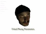
Moustache (Input)


Code Complete
I recently finished reading Steve McConnell’s “Code Complete”. In hindsight, I should have kept a list of all of the great things contained inside the book. The book is packed with information on software design and construction, lots of examples, and even more references to other sources. McConnell outlines the professional development plan used at his company, making it easy for anyone to get on a useful reading track.
And I have. I have read two of the references within this book (not necessarily in the professional development plan), and they have turned out to be worthwhile. The first was a classic, “How to win friends & influence people”, b Dale Carnegie. The other was, Conceptual Blockbusting.
Another related Amazon suggested reading was Donald Norman’s, “The design of everyday things”. I read most of this on my plane ride to Japan, and finished it this morning. It talks about all the things designers should (and shouldn’t do) to make products (or software) easy, intuitive, and just plain user-friendly. The book is comforting in the sense that it discusses how failure to use something (a tool, a software), is often the fault of bad design. Out of the book, some of the most important points of design are really what should be almost common sense; things like providing a clear mental model, making the system state visible, hiding functions that aren’t necessary for a task, and using standards. The book gives plenty of good references to everyday objects that were poorly designed (several examples of doors and faucets). And I was even surprised to read that the author uses (or used) emacs. I will definitely be coming back to this book the next time I (try) and design a UI.
-
You are currently browsing the archives.
Latest Movies


Random Movies