Posts Tagged c++
MeldShape

MeldShape is another application for generating random shapes. Although, unlike JShape, which produces shapes in an algorithmic way, MeldShape takes an initial set of shapes and evolves them using differential equations.
Each shape has a measure of speed over the domain, and tries to fill in the entire domain without conflicting with other shapes. There is also a measure of how much a shape can vary from its original shape. The evolution is performed using an implicit level-set implementation. More technical details: meldshape
Below there are binaries for both windows and Mac. The Mac version will require you to download a recent version of the open source Qt libraries. Open up the application, and drag a set of seed shapes from JShape onto the window. Use the evolve button to start the evolution.

The concept for this project was initiated for Mat Bushell.
Some movies of evolution:
And an unedited (poor quality) movie of how to use MeldShape in combination with JShape: meldshape-usage
Qt UiLoader runtime erros when cross-compiling
I was recently trying to build a windows version of the level-set shape generation (initial results, which is really a derivative of JShape), which is now titled MeldShape. The Mac version has come through several revisions now, and I figured if I was going to put anything up here, it might as well include everything (a document, some binaries, as well as a post).
Anyhow, I usually use a cross-compiler to build windows applications, and in the past I haven’t had any trouble getting a working build. However, this time was different.
I have working binaries for most of the libraries that MeldShape depends on, so building MeldShape was just a matter of updating these libraries and fixing any non-portable aspects within MeldShape. There were a few of these little things, like usleep and drand48, and checking validity of a pthread with (pthread_t*) != null (win32 pthread_t is a struct with a pointer inside). These things are obviously straightforward, and wouldn’t have even been an issue had I been thinking of a portable application in the first place. The real problem came within the Qt components.
When cross-compiling on linux for win32 targets, it is relatively straightforward to setup Qt. You use wine to install the windows libraries of Qt (the mingw build) and use your linux qmake with the appropriate spec file. Typically once you get the program to link you are out of the woods. But with Meldshape, linking was fine but running was always giving a symbol error in the Qt dll’s. It didn’t work either in Wine or in windows XP.
This was super frustrating, as I don’t have a working setup in windows using MinGW to build Qt applications. And in my experience, building in MinGW is really slow compared to the cross-compiler, so I really didn’t want to have to setup my environment from scratch (building from source). So I suffered through this problem, trying to figure out why on execution windows was complaining about missing symbols in the Dll (mostly in QtCore4.dll). I have seen similar problems to these when trying to run the executable with mismatched Dll’s (especially between the mingw and msvc builds of Qt), so I figured it had to be something with the versions of the Dll’s. I was using the same version as I had built with, so that was out.
I then tried an older version of Qt (since I had been using an older version in the past), and again no luck. With no other option, I started to strip my app to a barebones sample application to see if even that would work. And sure enough it was working fine (although it wasn’t referencing much else other than QApplication). The problem seemed to be something to do with one of the other libraries I was using.
I struggled with this for a while, and finally came up with the hypotheses that this was maybe due to loading parts of the UI with QUiLoader (from UiTools). After commenting out the few parts that use forms, it actually starts to work ???? This was at the point when I was ready to say, “screw the windows build”. I mean, the application is pretty simple, and at this point it is not even worth the effort. Anyway, I’m sure I am using forms in my other applications, so I have no idea at this point why using forms are causing problems with the Qt in windows. I decide to try QFormBuilder from the QtDesigner components instead. Luckily the API is pretty much the same, so almost no code (except for the declaration of the loader) has to change. Strangely enough, QFormBuilder worked fine.
I have no idea why QUiLoader was causing problems and QFormBuilder was not. I’m happy I found the problem, but at the same time I think the only reason I found it was due to luck. In the end it took almost 6 hours to find the problem and port the rest of the code…something I figured would take maybe 2 hours.
In the next little bit, I will try and upload the binaries and the technical document (as well as create a new project page for it)…all of the things that could have been done in that time it took to track down a non-sense bug.
Space-time texture map
There was a paper in 3DIM’09 entitled something like space-time consistent texture maps. The paper talks about how to construct a single consistent texture map from a multi-view video sequence of a moving subject. The method assumes as input a consistent triangular mesh (over all time sequences) and the input images. The problem is posed as a labelling problem: for each triangle compute the view (and time step) from which to sample its texture.
This framework obviously holds for the capture of static objects (where the number of labels is just equal to the number of images). This optimization framework is an alternative to other approaches, such as the naive solution of just averaging textures using all image observations. Such simple averaging does not work if the geometry is inaccurate (see image to the right of the blurry house, mostly on the side). I was curious if such a labelling approach would work better on approximate geometries, or whether it could be extended to a view-dependent formulation.
In the original formulation, the data term for a triangle in a view takes into account how much area is covered by the projected triangle (e.g., it prefers to assign a triangle to a view where it’s projected area is large). The smoothness term then takes into account the color differences along an edge. In other words if two triangles are labelled differently, then a labelling that has similar colors along the edge should be preferred. This problem can then be solved (approximately) with graph-cuts using alpha-expansions.
The last couple nights, for some reason, I kept having this thought that this same framework could be used to estimate some sort of view-dependent texture map (where instead of just finding the single best texture, you find several (say 4) texture maps that will work best in a view-dependent case). All that would need to be changed is the data term, and then incorporate some notion of view-dependent consistency (e.g., instead of just using the color difference on edges in the texture maps for neighbouring triangles, a similar cost could be measured on the edges after rendering from several views).
Basic implementation
I started implementing the basic framework. Below are some example results. Although, the method should really work best when used with accurate geometry, I wanted to test out the method when the geometry was only approximately known. In this sequence, the house is reconstructed using shape-from-silhouette, meaning that the concavities beside the chimney are not in the reconstructed geometry. Again, the image at the beginning of the blog (and at the right) show the results of simply averaging input images in the texture.
The left-most image shows the results with no smoothing (e.g., the best front-facing image is chosen for each triangle, followed by the solution using increasing smoothness weightings). There are some artefacts, especially on the left hand side of the house (by the chimney, where the geometry is incorrect). Increasing the smoothness helps out a bit, but too much smoothness samples the side regions of the texture from the front-facing images (which makes the blurry). See the movie to get a better idea of the problems.

Reconstructed textures for the house (left no smooth, right two increasing smoothness).
The texture maps for no smooth (best front-face image), smoothness=1, and smoothness=2, are given below. The gray-scale images show which input image the texture was assigned from (notice that the leftmost is patchy, where the right image suggests that large regions sampled texture from the same input image).
 |
 |
 |
 |
 |
 |
Dog results
I also tried this for a model where the geometry was much more accurate (the dog). It is hard to actually see any artefacts with the naive approach of just sampling the best view for each triangle (left-most image below).

Again, below are the corresponding texture maps and the gray-scale images denoting where the texture was sampled from. Again, increasing the smoothness definitely reduces the number of small pieces ni the texture. But it is hard to actually see any visually difference on the results. Check the video to see for yourself.
 |
 |
 |
 |
 |
 |
It is much easier to visualize the textures on the object. The blender models and reconstructed textures are uploaded if you want to check them out: models & textures.
View-dependent extensions
Shortly after implementing this, and before starting on the view-dependent extensions, I realized that I was going to run into some problems with the discrete labelling. If you have n images and you want to find a set of 4 view-dependent texture maps, you will need n choose 4 labels. Even with as few as 20 input images, this gives 4845 labels. After running into this problem, I didn’t further formalize the enery for the view-dependent case.
wtWidgets
Overview
This was my second attempt at a OpenGL UI toolkit (the first one being GWindows, used in the NES emulator). When I started, I was most concerned with adding animations, and how to interface with UI events. The events were handled using boost signals and slots, which is (in my opinion) the perfect way to implement UI events. The toolkit has customizable widgets (allowing for different fonts, backgrounds, and styles), as well as hooks for allowing animations to be attached. The toolkit has the typical windowing elements: windows, buttons (regular and check), menus, sliders, group boxes, layout managers, split panes, combo boxes, and text edits.
Most of the feel (of look and feel) is established by signals and slots. For example, upon creation a widget emits a look and feel signal, which allows for any slots (e.g., sounds or animations) to be attached to the widgets various UI signals (e.g., button pressed, window exiting, etc.). Backgrounds are controlled with textures and programmable shaders (old-school fragment programs that is).
Unfortunately, I wasn’t super concerned with usability, so laying out new widgets has to be done in code (and it is a little painful). The XML schema for styles could also use some work.
I have only used this code in a couple of projects. It is used in part of my Ph.D project for tracking humans (and one of the demos), and it is also coarsely integrated into the GT demo.
Styles
Here are a couple sample styles (follow links to view the movies: plain.flv style1.flv style2.flv).
 Style 2 (Aqua like) |
 Plane style |
 style1 |
|
Python Console

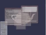
Part of the UI was developed in conjunction with a UI inferface to python (I call it PyCon; I realize this is also the name of a conference). The console allows commands to be issued from a command line prompt from within your program. All you have to do to use it is create the corresponding python wrappers for your classes (e.g., using boost::python, swig, sip, or whatever other tool you prefer. The low-level python console interface allows issuing commands (and auto-completing them). The UI is similar and wraps this low-level interface with a UI for issuing commands, displaying partial autocompleted results, scrolling through output, and remembering previously issued commands. I personally think that with the autocomplete, this is sometimes more useful than the actual python console.
Unfortunately, the python console will not work in windows (as it uses “dup” and “dup2” in order to grab the python interpreter stdin and stdout).
History
Although I can’t remember exactly what possessed me to start this project, I think it had something to do with seeing other nice interfaces (both in GL and for the desktop). One in particular was the original version of Beryl (or Desktop effects in Linux) that included the wobbly windows. I designed my own wobbly windows based on a spring network with cubic polynomial subdivision for rendering (wobbles: avi flv). This all started sometime around 2006, or 2007. See the source code (it may not be pretty: springs.cpp).

Iterative mesh deformation tracking

Patches on mesh (left) and a different target mesh
Another idea that interested me from ICCV (or 3DIM actually) was related to tracking deforming geometry, using only raw geometry no color. The paper in particular ( Iterative Mesh Deformation for Dense Surface Tracking, Cagniart et al.) didn’t require even geometric feature extraction, but rather relied on a non-rigid deformation scheme that was similar to iterated closest points (ICP). The only assumption is an input geometry that has the same topology of what you would like to track. As for the ICP component, instead of doing this for the entire model, the target mesh contributes a displacement (proportional to cosine between normals) to its closest vertex on the deforming source mesh. The source mesh is then partitioned into a set of patches, and each patch tries to compute a transformation that satisfies the point-wise constraints. The positional constraint on the patch center is then used in a Laplacian (or more specifically, the As-Rigid-As-Possible (ARAP) Surface deformation framework) to deform the geometry. This is then iterated, and a new partitioning is used at each frame. To ensure some more rigidity of the model, the positional constraint on the patch center is influenced by it’s neighboring patches, as well as by the transformation of the original source mesh. Look at the paper for full details.
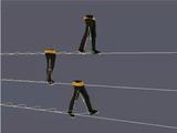
I needed the ARAP for some other project (see previous blog), and decided to go ahead and try to implement this (I think it was actually last Friday that I was playing around with it). Anyhow, this week I knew that I had to test it on some more realistic data; my first tests were of tracking perturbations of the same geometry (or of a deforming geometry with the same topology). To generate some synthetic data, I rendered 14 viewpoints of a synthetic human subject performing a walking motion (the motion is actually a drunk walk from the CMU motion capture database). For each time frame, I computed the visual hull and used the initial geometry to try and track the deforming geometry. This gives a consistent cross-parameterization of the meshes over the entire sequence.
After tweaking some of the parameters (e.g., the number of iterations, and the amount of rigidity, the number of patches), I was able to get some decent results. See some of the attached videos.
Links to movies (if the above didn’t work):
Source blender file (to create the sequence, some of the scripts I use often are in the text file): person-final-small
Image operation (shear/block/edge)
I got this idea for a cool image operation from an image in the book “Conceptual Blockbusting”. The seed image was basically just a bunch of sheared black and white rectangles. I wanted to create a similar image from some source image, but have a bunch of colored rectangles. I ended up using rotated and scaled rectangles. The result wasn’t near as good as I had hoped, but I figured since I wasted a little bit of time on it, that it was worth sharing. I tried adding edges as well. Didn’t work out all that great but whatever.
Check out the source code. It requires some code from a previous post on shock filtering, and it uses cairo to do the drawing (shear source code).


(non)-rigid tracking
In the past little while I have been trying to determine a way that dense geometric deformations can be reconstructed and tracked over time from a vision system. The main application is to track dense geometry deformations of a human subject over time so that they can be played back under novel view and animation conditions.
It is assumed there are only a few cameras (with known pose calibration) observing the scene, so it is desirable to take advantage of as much temporal information as possible during the reconstruction. As a simpler starting point for this problem, I felt it appropriate to work on the reconstruction of dense geometry for a moving human head.
Many existing tracking methods start with some known dense geometry, or assume that the geometry can be reconstructed at each time instant. In our case, neither of these assumptions hold, the latter because we have only a few cameras. The general problem is therefore to reconstruct a dense model, and its deformations over time.
A part of the problem is to reconstruct the motion of the rigid parts. This can be done using all available cues, e.g., texture and stereo. And it too can be accomplished with different representations (e.g., a set of points, a mesh, or level-sets). In these notes, I considered this problem alone: given an approximate surface representation for a non-rigid object, find the transformations of the surface over time that best agree with the input images. Keep in mind, however, that these ideas are motivated by the bigger problem, where we would like to refine the surface over time.
In this example, intensity color difference (SSD) tracking was used to track a skinned model observed from several camera views. The implementation is relatively slow (roughly 1 frame a second), but I have also implemented a GPU version that is almost 7 fps (for 12000 points and two bones, one 6.dof base/shoulders and a 3 dof neck, with 4 cameras).
There is a pdf document with more details posted as well.
Some videos are given below.
An example input sequence. The video was captured from 4 synchronized and calibrated cameras positioned around my head.
If we just run a standard stereo algorithm, we will get some noisy results. Ideally we would like to track the head over time and integrate this sort of stereo information in the coordinate frame of the head. This part is hard as the surface is open.
Tracking the head alone would allow the registration of these stereo results in a common coordinate frame, where temporal coherency makes more sense. The video below demonstrates this idea, although I haven’t found a good solution for merging the stereo data.
| Tracked head | Depth registered in coordinate frame of head |
The following videos are more related to the tracking using a skinned mesh and an SSD score. In the following videos the tracked result on the above input sequence using a mesh generated from the first frame is illustrated below. The mesh has two bones: one 6 D.O.F for the shoulders and another for the 3 D.O.F. neck/head.
The tracking currently ignores visibility; this can cause problems when many of the points are not visible. An example of this mode of failure is given in the following sequence. This sequence was captured under similar conditions, although the left-right motion is more dramatic (more vertices are occluded). Additionally, this sequence has some non-rigid motion.
| Input sequence | noisy depth from stereo |
| Tracked head and shoulders. Notice the failure when the head is turned too far to the left. | |
These videos, and the original avi’s are available in the following two directories:
seq0-movies and seq1-movies. You will need vlc, or mplayer, ffmpeg, (maybe divx will work) to view the avi’s.
Code for Rodrigues’ derivatives: roddie. Included as I merged this code into my articulated body joint.
Latest Movies


Random Movies